Real Time Application Design Tutorial
Using FreeRTOS in small embedded systems
If you came straight here then start by:
-
Viewing the Homepage to put this into context
-
Viewing the What is FreeRTOS page to see where FreeRTOS fits
<<< | >>>
HINT: Use the <<< and >>> arrows to navigate this section.
Introduction
This section provides a tutorial on writing applications that use an RTOS on memory constrained microcontrollers. It
is not a FreeRTOS specific tutorial. If you are looking for a specific FreeRTOS turorial, or a more complete
tutorial on using an RTOS in an embedded system, then the
FreeRTOS books
will be a more valuable resource.
This part of the web site presents four contrasting design solutions to a hypothetical embedded real time application.
The suitability of each solution is judged for embedded computers with varying RAM, ROM and processing
capabilities. In addition the simplicity and corresponding maintainability of each design is assessed.
This is not intended to present an exhaustive list of possible designs, but a guide to the ways in which the
FreeRTOS real time kernel can be used.
It should be noted that this section was written several years ago - when FreeRTOS was primarily used on
very small microcontrollers. Since that time it has become more common to use FreeRTOS on much larger
microcontrollers that are not so restricted in the ROM and RAM they provide.
NOTE: These pages have not yet been updated since the introduction of FreeRTOS V4.0.0. V4.0.0 introduces the concept of co-routines which would
provide a different and novel solution to those presented here. The Tasks and Co-routines documentation
provides further information.
The [hypothetical] Application
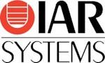
 System context [not to scale].
The application will execute on an embedded single board computer that must control a plant while maintaining both local and
remote user interfaces.
Depicted above, the system consists of:
- An embedded computer within a control terminal.
- Two fieldbus networked sensors.
- The plant being controlled (could be anything, motor, heater, etc.). This is connected on the same fieldbus network.
- A matrix keypad that is scanned using general purpose IO.
- Two LED indicators.
- An LCD display.
- An embedded web server to which a remote monitoring computer can attach.
- An RS232 interface to a configuration utility that runs on a PDA.
Top Level Software Requirements
Here we are interested in the sequencing and timing requirements, rather than the exact functional requirements.
Plant Control
Each control cycle shall perform the following sequence:
- Transmit a frame on the fieldbus to request data from the networked sensors.
- Wait to receive data from both sensors.
- Execute the control algorithm.
- Transmit a command to the plant.
The control function of the embedded computer shall transmit a request every 10ms exactly,
and the resultant command shall be transmitted within 5ms of this request.
The control algorithm is reliant on accurate timing, it is therefore paramount that these timing requirements are met.
Local Operator Interface [keypad and LCD]
The keypad and LCD can be used by the operator to select, view and modify system data.
The operator interface shall function while the plant is being controlled.
To ensure no key presses are missed the keypad shall be scanned at least every 15ms. The LCD shall update within 50ms of
a key being pressed.
LED
The LED shall be used to indicate the system status. A flashing green LED shall indicate that the system is
running as expected. A flashing red LED shall indicate a fault condition.
The correct LED shall flash on and off once ever second. This flash rate shall be maintained to within 50ms.
RS232 PDA Interface
The PDA RS232 interface shall be capable of viewing and accessing the same data as the local operator interface, and the
same timing constraints apply - discounting any data transmission times.
TCP/IP Interface
The embedded web server shall service HTTP requests within one second.
Application components
The timing requirements of the hypothetical system can be split into three categories:
- Strict timing - the plant control
The control function has a very strict timing requirement as it must execute every 10ms.
- Flexible timing - the LED
While the LED outputs have both maximum and minimum time constraints, there is a large timing band within which
they can function.
- Deadline only timing - the human interfaces
This includes the keypad, LCD, RS232 and TCP/IP Ethernet communications.
The human interface functions have a different type of timing requirement as only a maximum limit is
specified. For example, the keypad must be scanned at least every 10ms, but any rate
up to 10ms is acceptable.
NEXT >>> Solution #1: Why use an RTOS kernel?
Copyright (C) Amazon Web Services, Inc. or its affiliates. All rights reserved.
|